Beginners guide to Robotics
Introduction to PCB
Robo Explorers
Now lets have a look at how we engineers design the PCBS
Step 1
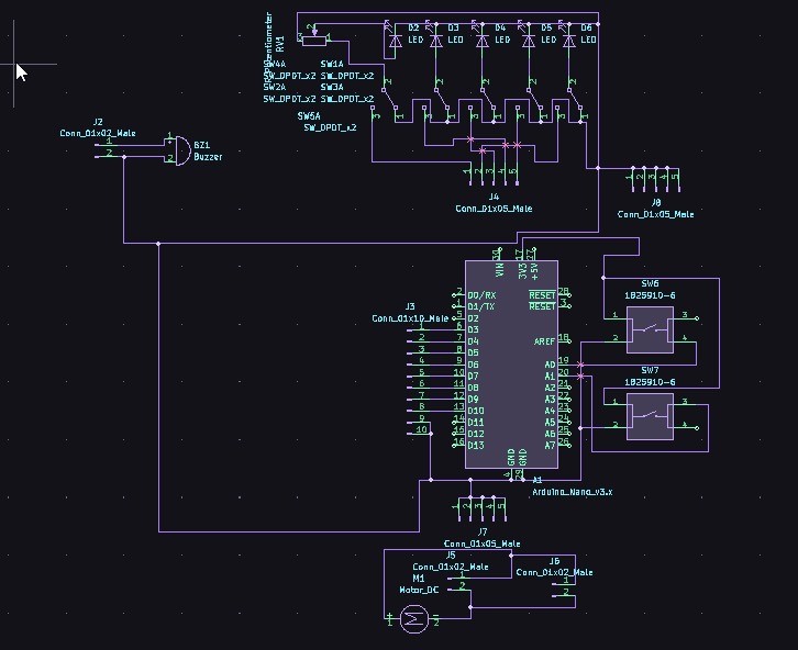
First we draw a diagram of our circuit which is called circuit schematic. This shows what component is connected to what, where and how! This schematic also helps fellow scientists and engineers to understand what circuit you have in your mind.
Step 2
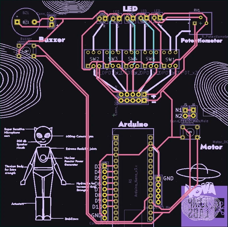
Then we will make the PCB layout. Where we will draw the electronic connections also called copper track routes which will connect our components all together in our board.
Step 3
Finally when we are done with these steps we just check if there is no error in our design and then just order the PCB!

Components of the Stellar Board
Your Yellow Tyro Board includes many components on it. We will talk about all the components in detail in the upcoming sections. Here is a small preview of what you will learn!
LEDS
DC Motor
Buzzer
Potentiometer
Switches
The Arduino!
They are placed and connected in such a way that makes our Yellow Tyro Board run Properly and help NOVA and team to escape the mysterious cave.

Learn from a Professional
Book a Class


