
Sea Voyage
Robo Explorers 2
Servo Motor
SG90 Servo Motor
A Tiny But Mighty Motor!
The SG90 Servo Motor is a small, precise motor that moves to a specific position instead of spinning continuously like a regular motor. Think of it like a robotic arm that can be told to move to an exact angle—great for robots, cars, and automation projects!
How Does a Servo Work?
Imagine you’re playing with a steering wheel on a toy car:
Control Arm = Steering Wheel: The servo's arm moves left and right, just like a steering wheel turning the car.
Signals Tell It Where to Move: The Arduino sends signals to tell the servo exactly which angle to turn to (like 0°, 90°, or 180°).
Power and Control Wires: The servo has 3 wires:
Red (VCC): Power supply (5V).
Black/Brown (GND): Ground connection.
Orange/Yellow (Signal): The Arduino sends signals through this wire to control movement.
The Physics Behind It
Imagine a robotic arm that can move to pick up a cup.
Inside the servo, there are tiny gears that precisely control how much the arm moves.
The Arduino sends pulses that tell the motor exactly how far to turn—just like telling a toy car how much to steer!
Understanding PWM (Pulse Width Modulation) and How It Controls a Servo Motor
When we control a servo motor or adjust LED brightness, we don’t just send "ON" or "OFF" signals. Instead, we use PWM (Pulse Width Modulation), a special technique that lets us create smooth and controlled movements. Let’s break it down!
What is PWM?
PWM stands for Pulse Width Modulation. It’s a way to control the amount of power sent to a device by turning it ON and OFF really fast—so fast that the human eye or a motor doesn’t notice the blinking, but instead sees smooth motion or dimming.
Think of it like a fan speed control:
🔹 If you give the fan full power, it spins fast.
🔹 If you give it half power, it spins slower.
🔹 If you keep switching the power ON and OFF really fast, you can control how fast it moves!
This is exactly how PWM works.
Duty Cycle – The Key to PWM
The most important part of PWM is the Duty Cycle.
A duty cycle is the percentage of time the signal is ON versus OFF in each cycle.
Example of Duty Cycles:
Duty Cycle | Meaning |
|---|---|
100% (Always ON) | Full power (e.g., LED fully bright, motor at max speed) |
50% (Half ON, Half OFF) | Half power (e.g., LED at medium brightness, motor at half speed) |
25% (Mostly OFF) | Low power (e.g., LED dim, motor moving slowly) |
0% (Always OFF) | No power (e.g., LED off, motor stopped) |
How PWM Controls a Servo Motor
A servo motor doesn’t just spin like a normal motor—it moves to an exact position between 0° and 180° based on the PWM signal it receives.
The Arduino sends a PWM signal to the servo’s signal wire (usually on pin 9 or 10), which tells it what angle to move to.
Servo Timing with PWM
For an SG90 servo, the PWM signal works like this:
Pulse Width | Servo Angle |
|---|---|
0.5ms | 0° (Leftmost position) |
1.5ms | 90° (Middle position) |
2.5ms | 180° (Rightmost position) |
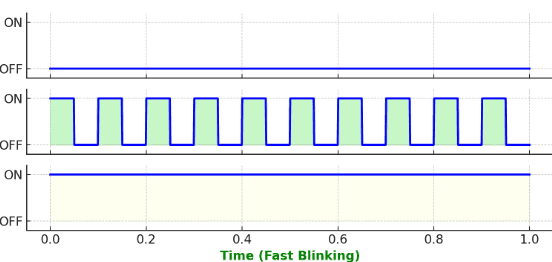
What’s Happening in the Graph?
🔹 Top Line (0% PWM) → Servo Stays Still at 0° (Leftmost Position)
The signal is almost always OFF (very short pulses).
The servo doesn’t move much—it stays all the way left.
🔹 Middle Line (50% PWM) → Servo Moves to 90° (Middle Position)
The signal is ON and OFF equally.
The servo moves halfway and stays in the center.
🔹 Bottom Line (100% PWM) → Servo Moves to 180° (Rightmost Position)
The signal is almost always ON (very long pulses).
The servo moves all the way to the right.
How to connect servo motor on the Blue Elixer Board
Code Snippet Breakdown
Pin Setup – Telling Arduino Where the Servo Is
What’s happening?
Include the Servo library (
#include <Servo.h>) so we can control the motor.Create a Servo object (
Servo myServo;) to control the motor.Attach the servo to pin 9 (
myServo.attach(9);) so the Arduino knows where to send signals.
Moving the Servo to Different Positions
What’s happening?
The servo moves to 0°, 90°, and 180° in a loop.
The
delay(1000);command makes it wait for 1 second before moving again.
Fun Activity!
In this fun activity, we will make a servo motor sweep back and forth from 0° to 180° in 10 steps! Think of it like a robot waving hello or a radar scanning the area!
You'll see how PWM controls movement smoothly, making the servo move in steps instead of jumping instantly. Ready? Let’s code!
The Code: Sweeping the Servo!
Code Breakdown (How It Works!)
Including the Servo Library
This allows the Arduino to easily control the SG90 Servo Motor.
Creating the Servo Object
This creates a servo object that lets us control the motor.
Setting Up the Servo in the setup() Function
The attach(9) command tells the servo motor which pin it’s connected to.
Sweeping the Servo from 0° to 180°
What happens here?
✅ The loop starts at 0° and increases by 20° each time until it reaches 180°.
✅ The servo moves in 10 steps (0, 20, 40, 60, 80... up to 180°).
✅ The delay(500); makes sure the servo moves smoothly (waits 500ms between movements).
Sweeping the Servo Back to 0°
What happens here?
✅ The servo now moves back from 180° to 0° in the same 10-step pattern.
What You’ll See!
The servo motor will smoothly sweep from 0° to 180° in 10 steps.
Then, it will sweep back from 180° to 0°, repeating forever!
It will look like a robot arm moving, a windshield wiper, or a radar scanner! 🦾
Fun Challenges for You!
1️⃣ Can you change the number of steps? (Try 5 steps or 20 steps!)
2️⃣ Make the servo move faster or slower by changing the delay time!
This is how real robots move—now you’re controlling one!